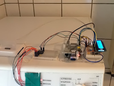
Welcome to the final part of the the mini series of postings on my Raspberry Pi project, the tumble dryer remote display. So far there has been the introduction, a posting on the concept and building of the hardware interface, and one part on the software I am using to make the remote display work. So, what is left? Well, as the whole thing can be called a "working prototype" there is plenty of room for change and improvement.
Amongst the possible improvements is the plan to make the HTML output look a little bit more like an actual display. As the program only inserts a given text into the HTML data, depending on the dryer's LEDs' status, it is easy to put the link to an image there instead. While I have no idea yet as for how to display the possible errors, I will prepare five images, based on the one that can bee seen on the right. Instead of the dark bars there will be red ones, depending on the status that has been detected. The code will be changed to insert the link to the appropriate picture. Text will only be used to cover the cases where there is no appropriate image available. I have no idea about the temperature section yet.
Another change I am currently thinking about (and I hesitate to call it a possible improvement, with reason) is to turn the passive, on-request remote display into a more active one. While adding a cell phone to the setup and make the Raspberry Pi send an SMS sure would work, making the remote display "tweet" might turn out to be the feature more likely to be implemented. I came across Python Twitter which could fit in well. As I am using Twitter clients that support notifications, sending a direct message to my Twitter account would be almost like sending an SMS to my cell phone. Amongst other things that would need to be changed, I would have to check if the status has changed since the last run: receiving a DM once per minute would not be exactly helpful, not to mention Twitter API limits. And a direct message sent only once after a status change has been detected could easily be overlooked. After all, this would be more just for the fun of it than anything else, mostly depending on the amount of time that would be needed to add the Python Twitter features. A tweeting tumble dryer - think about it.
Something that could turn out to become an actual improvement would be turning the cron job-triggered program into some kind of "self-contained" demon. While the current solution is a more passive one, as it simply produces/updates a HTML file once per minute, a future version could bring its own web server (using Python's http.server module) and a more "interactive" version of the core script which would only update the data if the page is (re-)loaded. The demon itself would check if the required hardware is available: if so, it would stay in the running state and answer requests, and if not, it would simply die. At the moment this is just a fuzzy idea, but who knows.
A change to the current setup that is almost certain to happen is that I am going to add a DHT22/AM2302 digital temperature and humidity sensor. The DS18S20 available at the moment can only be used to tell the temperature in/around the case of the prototype mounted on the tumble dryer's control panel. Adding a sensor that could be placed somewhere away from the dryer itself would make more sense, or at least it could help judging if the bathroom's window should be opened or closed. As the AM2302 cannot be connected to the 1-Wire bus available, adding this component could be fun. Famous last words, I know. The software needs a little bit of attention of course as there will be one device (with two additional sensor values) that needs to be taken care of. No problems, only solutions.
That pretty much sums it up, at least for the moment of writing this posting.
I hope you enjoyed reading about my tumble dryer remote display. If you have questions or comments, both are welcome! And maybe the small series of postings sparked your imagination what can be done with a Raspberry Pi, a handful of electronic components and a few lines of code. If so, go and create! I would love to hear about your projects!
Sunday, November 10, 2013
Tumble Dryer Remote Display - Part III
Welcome back to the third of my four part series on the tumble dryer remote display, a small project of mine, based on the Raspberry Pi. While in part one I tried to give you the idea what this is all about, the last posting was on the hardware of the interface. This time I will cover the software I created to read and interpret the data from the interface and build some sort of display from that. The final part will give some kind of outlook on where I (or maybe you, too) could be going from here by describing ideas and possible options that could improve the current version of the tumble dryer remote display. But first things first.
Shortly after getting my first Raspberry Pi, I decided to go with Adafruit's Raspberry Pi Educational Linux Distro for my electronic projects. I started using Occidentalis mostly because the changes I would have had to make for using it for what I had in mind were already done in this distro. While it wouldn't make much sense to use it "in the wild", it is perfect to just get started. (If you are new to the Raspberry Pi you might find Adafruit's Learning System section on it helpful, or at least interesting.) So an up-to-date version of Occidentalis v0.2 is what I used for this project.
One of the basic ideas for the software I wanted to build to do the actual remote display job was born when I was playing around with a DS18S20 temperature sensor and the 1-Wire bus shortly after getting the Raspberry Pi. The nice thing about using said bus is that the related (driver-)package presents the relevant data using what is called the the 1-Wire File System (OWFS): reading sensor data is as easy as reading from a file. So I created a very raw shell script that reads the file for the appropriate sensor, gets the temperature from it, and compile a simple HTML file with the data. Using the Apache web server of the running Linux distro and a simple cron job that triggered the shell script on a regular basis, I could check the temperature from any browser on my network.
A word of warning: since I was writing the file directly to the /var/www directory (instead of a job-related subdirectory) I had to update the permissions there - if I remember correctly. Since the whole "solution" was only meant to run on a protected network at home I neither was nor am concerned about the security issues here. But it is far from being even close to "best practice"! Please keep that in mind in case you are thinking about creating a similar project.
For the tumble dryer remote display, the basic approach for me was:
I decided to use Python to write the script needed, mostly out of curiosity because I am new to it and there is nothing like a specific problem to solve to start learning a new programming language. (It is easy to tell that I am neither an experienced programmer nor a Python Pro by having a look at the code - either at the end of this posting or by downloading the file.)
For the test runs of the first prototype I used some lines of code I had found in the thread Grumpy Mike's instructions for PCF8591 at the Raspberry Pi Forum. Parts of that code can still be found at the core of my script's function that deals with the I²C-bus device. It really helped me to understand what I was actually trying to do there. Apart from that, the step to create some basic data logging wasn't that big any more. The data collected was very important to answer the question which values represented an LED that was actually on, compared to LEDs that were off at the same moment.
Working out what I wanted to achieve with the program and thinking of ways to do so, I decided that for the time being I could live with detecting only few things of the setup "automatically". As I am planning to use the interface hardware in combination with different Raspberry Pis, a function to detect the revision number of the board is quite a nice thing to have. (It is actually important as the ID of the I²C-bus depends on it.) Apart from that one, the other values needed are hard coded, but I tried to keep the program manageable by assigning them to global variables (in the top section of the code). The most important ones are:
Shortly after getting my first Raspberry Pi, I decided to go with Adafruit's Raspberry Pi Educational Linux Distro for my electronic projects. I started using Occidentalis mostly because the changes I would have had to make for using it for what I had in mind were already done in this distro. While it wouldn't make much sense to use it "in the wild", it is perfect to just get started. (If you are new to the Raspberry Pi you might find Adafruit's Learning System section on it helpful, or at least interesting.) So an up-to-date version of Occidentalis v0.2 is what I used for this project.
One of the basic ideas for the software I wanted to build to do the actual remote display job was born when I was playing around with a DS18S20 temperature sensor and the 1-Wire bus shortly after getting the Raspberry Pi. The nice thing about using said bus is that the related (driver-)package presents the relevant data using what is called the the 1-Wire File System (OWFS): reading sensor data is as easy as reading from a file. So I created a very raw shell script that reads the file for the appropriate sensor, gets the temperature from it, and compile a simple HTML file with the data. Using the Apache web server of the running Linux distro and a simple cron job that triggered the shell script on a regular basis, I could check the temperature from any browser on my network.
A word of warning: since I was writing the file directly to the /var/www directory (instead of a job-related subdirectory) I had to update the permissions there - if I remember correctly. Since the whole "solution" was only meant to run on a protected network at home I neither was nor am concerned about the security issues here. But it is far from being even close to "best practice"! Please keep that in mind in case you are thinking about creating a similar project.
For the tumble dryer remote display, the basic approach for me was:
- let cron demon trigger a piece of software
- that collects and interprets the data,
- then creates a HTML file from that
- which can be accessed through the web server.
I decided to use Python to write the script needed, mostly out of curiosity because I am new to it and there is nothing like a specific problem to solve to start learning a new programming language. (It is easy to tell that I am neither an experienced programmer nor a Python Pro by having a look at the code - either at the end of this posting or by downloading the file.)
For the test runs of the first prototype I used some lines of code I had found in the thread Grumpy Mike's instructions for PCF8591 at the Raspberry Pi Forum. Parts of that code can still be found at the core of my script's function that deals with the I²C-bus device. It really helped me to understand what I was actually trying to do there. Apart from that, the step to create some basic data logging wasn't that big any more. The data collected was very important to answer the question which values represented an LED that was actually on, compared to LEDs that were off at the same moment.
Working out what I wanted to achieve with the program and thinking of ways to do so, I decided that for the time being I could live with detecting only few things of the setup "automatically". As I am planning to use the interface hardware in combination with different Raspberry Pis, a function to detect the revision number of the board is quite a nice thing to have. (It is actually important as the ID of the I²C-bus depends on it.) Apart from that one, the other values needed are hard coded, but I tried to keep the program manageable by assigning them to global variables (in the top section of the code). The most important ones are:
- the I²C-bus address of the A/D converter and
- the 1-Wire bus address of the temperature sensor.
The current version of the script is made up from the functions taking care of:
- the revision number of the Raspberry Pi board [getBoardRevision()],
- the data from the temperature sensor [readTemperature()] (a kind of bonus),
- the data from the A/D converter [readDisplays()] (basically what it all is about),
- the converting of collected data into HTML code [buildHtmlFile()] (for the remote display).
The program uses the functions above to prepare and finally write the HTML code for the remote display to a file (/var/www/trocknerdisplay.html). On top of that, there is (still) a very basic function (doLogging()) to do some logging for testing and debugging.
I am using the system's cron demon to run the program once per minute; the HTML file created will make the browser reload it once per minute, too. That way the remote display page is pretty much up-to-date most of the time. (I added the information when the HTML file has been updated at the bottom of the page which allows to see if the job itself did really run or if there is something wrong with it.)
Even though the text in the picture is in German, I am sure that it gives you the idea what the actual output looks like. (It is a screenshot made on an iPhone.) I have to admit that the layout might need some work. But for the moment it is - adequate.
Now that I have told you how the code works (or at least how I have found it to work for me so far) I should tell you about the tiny specialties I implemented. I cannot tell you about "best practice" here as I am not an professional or even an experienced programmer. All I can say is that I found those specialties quite helpful.
One thing you might have spotted is that I am using "special" values throughout the script, like 9999 if the Pi's board revision number could not be identified, or -99 if the communication with the interface failed. While I tried to write the code to handle those failures as gracefully as possible, the "special" values are interpreted too, and the appropriate hint is used to replace the status information in the output file (for the dryer as well as for the temperature).
The other thing I would like to point at is that I actually create the value that represents the status of the dryer's control panel LEDs, instead of using a one-time result. Having a look at a log file I found that the values of each of the A/D converters channels would hardly ever be exactly the same in a series of readings, even if the status of the corresponding LED had not changed. Further more, it could be the case that the LED status either just changed while reading or that it changed shortly before or after reading the channel's value. The idea here is to check all channels multiple times (25 times in the current code) and using the average value as the basis for interpretation.
Now that you know about the code I am using (at the moment), and about the hardware interface I created, you can see what the tumble dryer remote display is and how it works. In the final part of this series I will tell you about the changes I already have in mind, about some ideas I have what else could be done with the current setup, and which options I can think of that might be interesting or helpful if implemented.
For those who prefer having a look at the code here instead of downloading it, well, here you go. (The syntax highlighting is far from perfect, but it should work for most of the lines below.)
#!/usr/bin/env python """file name: dryer_remote.py read status leds from tumble dryer via ldrs/pcf8591 over i2c and temperature via ds18s20 over 1-wire. sensor box and script designed to work on/with raspi (model b), board revision will be detected, the bus id will be adjusted accordingly. (this feature hasn't been tested yet.). id of 1-wire slave ds18s20 not checked in this version, so it has to be adjusted in the global init section below. parts of the script (reading from an i2c device) taken from raspi forum at http://is.gd/WW8c8q and from raspberry pi spy at http://is.gd/sdP911 (reading the baord's revision number). file created by LordGU, 01.11.2013 last modified by LordGU, 06.11.2013 """ # import needed libraries import smbus import time # global init readValues = [-1,-1,-1,-1,-1,-1,-1] w1DeviceId = "10-000802542123" i2cAddress = 0x48 boardRevDefault = "0000" # reading board revision number # def getBoardRevision(revisionFallback): # Extract board revision from cpuinfo file thisBoardRevision = revisionFallback try: with open('/proc/cpuinfo','r') as cpuinfofile: for line in cpuinfofile: if line[0:8] == 'Revision': length=len(line) thisBoardRevision = line[11:length-1] cpuinfofile.close() except: thisBoardRevision = "9999" return thisBoardRevision # temperature stuff goes here # def readTemperature(tempSensorId): thisTemperature = 0 try: # adjust path for id of used sensor if needed with open("/sys/bus/w1/devices/" + tempSensorId + "/w1_slave","r") as w1tFile: fileText = w1tFile.read() thisTemperature = float(fileText.split("t=")[1]) / 1000 w1tFile.close() except: thisTemperature = -99 return thisTemperature # i2c stuff goes here # def readDisplays(checkBus,checkAddress): # init displayValues = [0, 0, 0, 0] n_samples = 25 thisBusId = 0 runChecks = False # set bus id if (checkBus == "9999"): thisBusId = 99 runChecks = False elif (checkBus == "0002") or (checkBus == "0003"): thisBusId = 0 runChecks = True else: thisBusId = 1 runChecks = True bus = smbus.SMBus(thisBusId) try: # check if a device is available at "checkAddress" bus.write_quick(checkAddress) except: runChecks = False if runChecks: for b in range(0,n_samples): # repeat for all for input ports of chip for a in range(1,5): # select input of chip at "checkAddress" and read from port bus.write_byte(checkAddress, (0x40 | a) ) displayValues[a-1] = (displayValues[a-1] + bus.read_byte(checkAddress)) time.sleep(0.05) for c in range(0,4): displayValues[c] = displayValues[c] / n_samples else: displayValues = [-99, -99, -99, -99] return displayValues # html stuff goes here # def buildHtmlFile(computedValues): #init htmlDocument = [] ledOnOff = 100 pollError = -99 htmlDocument.append( """<!DOCTYPE HTML PUBLIC "-//W3C//DTD HTML 4.01 Transitional//EN" "http://www.w3.org/TR/html4/loose.dtd"> <html>""" ) htmlDocument.append( """<head> <title>RasPi Trockner-Monitor</title> <meta http-equiv="Content-Type" content="text/html; charset=utf-8"> <meta http-equiv="refresh" content="60"> </head>""" ) htmlDocument.append( """<body> <h1>Trockner-Monitor</h1> <h2>Trockner-Status</h2> <p>""" ) if ((computedValues[2] == pollError) and (computedValues[3] == pollError) and (computedValues[4] == pollError)): htmlDocument.append("Fehler bei der Abfrage") elif ((computedValues[2] < ledOnOff) and (computedValues[3] < ledOnOff) and (computedValues[4] < ledOnOff)): htmlDocument.append("nicht in Betrieb") elif ((computedValues[2] > ledOnOff) and (computedValues[3] > ledOnOff) and (computedValues[4] < ledOnOff)): htmlDocument.append("Betriebsbereit") elif ((computedValues[2] > ledOnOff) and (computedValues[3] < ledOnOff) and (computedValues[4] < ledOnOff)): htmlDocument.append("Trocknen") elif ((computedValues[2] < ledOnOff) and (computedValues[3] > ledOnOff) and (computedValues[4] < ledOnOff)): htmlDocument.append("Abkühlen") elif ((computedValues[2] < ledOnOff) and (computedValues[3] < ledOnOff) and (computedValues[4] > ledOnOff)): htmlDocument.append("Ende") else: htmlDocument.append("Störung") htmlDocument.append( """</p> <h2>Temperaturwert</h2> <p>""" ) if (computedValues[6] == pollError): htmlDocument.append("Fehler bei der Abfrage") else: htmlDocument.append((str(computedValues[6]) + " °C")) htmlDocument.append( """</p> <hr> <p>Letzte Aktualisierung: """ ) htmlDocument.append((computedValues[0] + ", " + computedValues[1] + " bis " + computedValues[7] + " Uhr")) htmlDocument.append( """</p> </body> </html>""" ) return htmlDocument # debug logging is done here - if activated # with adjustments: could be used to do error logging, # def doLogging(logValues): try: with open("/var/log/tumbledryer.log","a") as logFile: logFile.write(str(logValues)) logFile.write("\n") logFile.close() except: pass # something could be really wrong then # _main_ # readValues[0] = time.strftime("%d.%m.%Y") readValues[1] = time.strftime("%H:%M:%S") readValues[2:5] = readDisplays(getBoardRevision(boardRevDefault),i2cAddress) readValues[6] = readTemperature(w1DeviceId) readValues[7] = time.strftime("%H:%M:%S") try: # write the HTML file with open("/var/www/trocknerdisplay.html", "w") as htmlFile: htmlOutput = buildHtmlFile(readValues) for line in range(0,len(htmlOutput)): htmlFile.write(htmlOutput[line]) htmlFile.close() except: pass # maybe some error logging would make sense here # only for testing and debugging # # doLogging(readValues) #print(readValues) # EOF
Friday, November 8, 2013
Tumble Dryer Remote Display - Part II
This is the second part in a short series of postings on a small project of mine, which is based on a Raspberry Pi: a tumble dryer remote display. In the first part I told you what led to the idea of the device itself, and why I used a Raspberry Pi to build it. This post will be (mainly) about the hardware I use, and I will try to explain the "design". Part three describes the software (aka "short Python script", actually) that makes use of this interface.
One of the most important aspects to me regarding the remote display has always been that there should be - if any - a minimum of tinkering with the dryer's electronic. The control panel is pretty simple, it uses red LEDs to indicate the current status. Sadly it was less easy than expected to remove the panel, to be honest I lost my patience in trying to do it and gave up on this. Instead, I decided to find a way to actually "read" the LEDs, or at least those that are of interest to me. (Those would be the top three in the picture on the right; roughly translated: drying, cooling down, finished.)
Since the LEDs don't provide a consistent brightness to indicate a high level (or "on") status I had to choose between two options to monitor them: either phototransistors or light dependent resistors (LDRs), each of them with the need for additional parts to make the detection circuit work. I decided to use LDRs, along with an A/D converter, as it appeared to me that this would be the easier and more flexible solution to create. The "reader" circuit would be quite simple, and the work would be done by a program running on the Raspberry Pi.
At that point another decision had to be made: how to connect said circuit to the computer? The GPIO connector offers quite some options. Out of curiosity I looked for A/D converters that could possibly work for me in the setup I was thinking of. I finally went for the Philips/NXP PCF8591P, mostly because it could be used with 3.3V, which definitely a plus when using it with a Raspberry Pi without an additional level shifter - and it was the converter my preferred electronic component reseller offered back then. This decision led me to the answer to the initial question: I would use the Raspberry Pi's I²C-bus.
Finally, after reading the converter's data sheet, looking up some details and ordering the needed parts, the circuit for the first prototype was ready to be built. The picture on the right shows the breadboard with the basic components, ready to go, with one LDR. (Power and I²C-bus connections to the Raspberry Pi missing.) - Sadly it took me almost a year (yes, a whole year) to return to this project.
Two weeks ago the prototype was finished, and after some basic tests I wanted to find out whether it would really help me in building that tumble dryer remote display or not. So, while there was laundry in the washing machine I prepared the dryer. The whole thing looked a bit crazy, to say the least…
… But it worked! It worked as expected. Using this prototype and a very basic Python script I logged the values of each of the A/D converter's channels (each of them connected to an LDR, thus "reading" one status LED of the dryer) while the machine was doing its job. At the end of the laundry day I was really pleased to see that it was possible to use the collected data to the tell the dryer's status.
An additional result from the logging session was that ambient light conditions would be something I would have to take care of, either by the interface's design, or by the software that would have to deal with the data - or both. I was lucky that this day had brought a lot of changes for said conditions, so their impact on the data was pretty easy to be spotted. The only way to find out if the whole idea could still work for the remote display was to create another prototype, put it in a proper case, place it on top of the control panel - and run some more tests.
At that point I decided to add a Dallas/Maxim DS18S20 via the 1-Wire bus to the setup to track the temperature in the bathroom. It can get quite warm in there while the dryer is running, so I thought it would be quite helpful to get the idea when to open the window - or shut it again, when it would get too cold in the room. (Apart from that I had one of those ICs left after I had finished another "monitoring solution", based on this small project.)
After placing the whole circuit in its new case (with the piece of wire-wrap board that can be seen in the picture hardly more than a square inch in size) and placing it on the dryer's control panel (using Tesa Powerstrips) I ran another round of logging while the machine was running.
This time the ambient light seemed to have had way less impact on the logged values. The case did a great job, all sensors were in a good position, the data looked good enough to make a program deal with it. So the next step was to do exactly that: write the code that would fetch the data from the A/D converter via the I²C-bus, interpret it and make the results available - in some way. That is what part three is about.
To round off this part, attached below are images of the plugging chart (for the breadboard-based prototype) and the schematic of the circuit, both created with the Fritzing application. (Feel free to download dryer_monitor.fzz.) It has been the first time that I tried to use the application. The results sure could be better, but at least they are not hand-drawn.
Comparing the picture of the two prototypes above with the chart and schematic below, you will spot two differences, as I used
- a socket with integrated capacitor for the converter IC (as I was going to use a socket anyway, this version came in handy), and
- a resistor network (5 pins, 4 x 1k Ω) instead of discrete ones as pull down resistors for the converter's input ports.
Now that you know about the working interface prototype I am using at the moment to "read" the tumble dryer's local display, in part three (which will be available soon) you will find out about the software (yes, that "short Python script" I mentioned earlier) that interprets the A/D converter's data and creates the actual remote display.
As I said before: laziness can be a wonderful thing!
Tumble Dryer Remote Display - Part I
If you have read any of my previous posts here I don't break a secret when I tell you that I am lazy. Yes, I am lazy. Well, basically it is one of the prerequisites to be good at what I do for a living. Apart from that I am convinced that a lot of good ideas and helpful inventions are - to some extend - based on (personal) laziness. We are surrounded by (more or less) little helpers that make a lot of tasks and parts of our everyday life easier. And one or two of those things could use some improvement.
Like my tumble dryer. It sure is one of those things that really make my life easier, yet I prefer to keep this minion in a place that isn't my living room or home office. Along with my washing machine, the tumble dryer can be found in a corner of my bathroom. While this is overall quite convenient it has one tiny drawback: because it cannot (or at least hardly) be heard it while it is running, the only way to find out whether it has finished its job or not is to get up, walk to the bathroom and have a look.
Over the months I have thought of different ways that could have solved this serious problem, but as most of them would have either included drilling holes through walls, running cables, tinkering with the dryer's electronics or a combination of those, none of them has ever seen the light of day. The ideal way I could think of was a an non- or minimal invasive approach, especially as far as the tumble dryer was concerned, in combination with some sort of wireless connection to some kind of remote display.
When the Raspberry Pi became available, I decided that I had to get at least one. I loved the idea of this small computer device, and even though it came with loads of limitations, what I could be used for was (and is, of course) mostly limited by the imagination of those who use it. I was pretty curious (with curiosity at almost the level as laziness) and the weeks from putting my name on the waiting lists to the days when the order confirmation was received had been pure torture, not to mention the weeks until the two precious devices had arrived.
After getting familiar with the Raspberry Pi, I bought a cover for it, some small breadboards, kind of stocked up on basic electronic components and started playing around with what so far has been one of the greatest features this computer offers: the GPIO connector. A complete, Linux-based system that could be used to connect to and control - almost anything. Almost anything? Almost anything. Like a tumble dryer.
As might have guessed by now, the tumble dryer remote display is no longer an idea. It is a working prototype, the hardware as well as the software. And as I have been asked to write about it, well, that is why this piece you are reading exists. So, if you are interested in what it all is about and how it is done I will tell you in the following parts I am going to write/compile over the next days (or weeks). This is the basic idea of the series of postings:
Before you jump to one of the next parts and continue reading, let me give you a fair warning: when it comes to electronics and programming I am just a hobbyist. That said, the whole project and its hardware and software prototypes are far from being "best workmanship". But it was fun creating the whole thing and I have learned a lot, not to mention the ideas that appeared through the whole process of creating that tumble dryer remote display.
So, maybe some of you, after reading about it all, can imagine that it could be fun to do something like that themselves. Let me tell you: it is! Creating something that solves a problem, something that actually works is just great, an invaluable experience. It can be fun.
Laziness can be a wonderful thing!
Like my tumble dryer. It sure is one of those things that really make my life easier, yet I prefer to keep this minion in a place that isn't my living room or home office. Along with my washing machine, the tumble dryer can be found in a corner of my bathroom. While this is overall quite convenient it has one tiny drawback: because it cannot (or at least hardly) be heard it while it is running, the only way to find out whether it has finished its job or not is to get up, walk to the bathroom and have a look.
Over the months I have thought of different ways that could have solved this serious problem, but as most of them would have either included drilling holes through walls, running cables, tinkering with the dryer's electronics or a combination of those, none of them has ever seen the light of day. The ideal way I could think of was a an non- or minimal invasive approach, especially as far as the tumble dryer was concerned, in combination with some sort of wireless connection to some kind of remote display.
When the Raspberry Pi became available, I decided that I had to get at least one. I loved the idea of this small computer device, and even though it came with loads of limitations, what I could be used for was (and is, of course) mostly limited by the imagination of those who use it. I was pretty curious (with curiosity at almost the level as laziness) and the weeks from putting my name on the waiting lists to the days when the order confirmation was received had been pure torture, not to mention the weeks until the two precious devices had arrived.
After getting familiar with the Raspberry Pi, I bought a cover for it, some small breadboards, kind of stocked up on basic electronic components and started playing around with what so far has been one of the greatest features this computer offers: the GPIO connector. A complete, Linux-based system that could be used to connect to and control - almost anything. Almost anything? Almost anything. Like a tumble dryer.
As might have guessed by now, the tumble dryer remote display is no longer an idea. It is a working prototype, the hardware as well as the software. And as I have been asked to write about it, well, that is why this piece you are reading exists. So, if you are interested in what it all is about and how it is done I will tell you in the following parts I am going to write/compile over the next days (or weeks). This is the basic idea of the series of postings:
- Part I - introduction to the tumble dryer remote display
- Part II - concept of the hardware interface and building the prototypes
- Part III - reading the interface input, creating a basic remote display
- Part IV - a kind of outlook what might come next, ideas, possible options
Before you jump to one of the next parts and continue reading, let me give you a fair warning: when it comes to electronics and programming I am just a hobbyist. That said, the whole project and its hardware and software prototypes are far from being "best workmanship". But it was fun creating the whole thing and I have learned a lot, not to mention the ideas that appeared through the whole process of creating that tumble dryer remote display.
So, maybe some of you, after reading about it all, can imagine that it could be fun to do something like that themselves. Let me tell you: it is! Creating something that solves a problem, something that actually works is just great, an invaluable experience. It can be fun.
Laziness can be a wonderful thing!
Subscribe to:
Posts (Atom)